Features of S6062-05/10 Series Electric Control Actuator
- Cast aluminium stand, light volume, easy for transportation and installment.
- Synchronic reversible motor, hysteresis clutch separates the motor output shaft and drive part when reaching limiting position, then protecting the motor.
- High accuracy, fast reaction, supply for valve position feedback signal.
- Standard manual control function.
Technical Datasheet of S6062-05/10 Series Electric Control Actuator
| Model |
S6062-05/10A |
S6062-05/10D |
| Action |
Direct or reverse |
Reversible |
| Control |
Proportional |
Incremental |
| Input signal |
0~10V,2~10V; 0~20mA,4~20mA |
――― |
| Output signal |
0~10V,2~10V; 0~20mA,4~20mA |
|
| Motor |
Synchronic and reversible |
| Rating |
24VAC 50/60Hz 3W |
| Consumption |
3W |
| Force |
500N/S6062-05 ; 1000N/S6062-10 |
| Material(all types) |
Gear: nylon Support base: galvanized steel plateBracket: die cast aluminium Cover: ABS engineering plastics |
| Protection |
IP40 or IP42 |
| Full stroke time(25mm) |
100S |
| Actuator biggest stroke |
25mm |
| Ambient temperature(all types) |
-20~+50° |
| Relative humidity |
90% non condensing |
| Net weight |
0.72Kg |
0.66Kg |
Remark: The actuator connection by PG joint after derivation, the protection grade could be IP42.
PCB Board Drawing of S6062-05/10 Series Electric Control Actuator
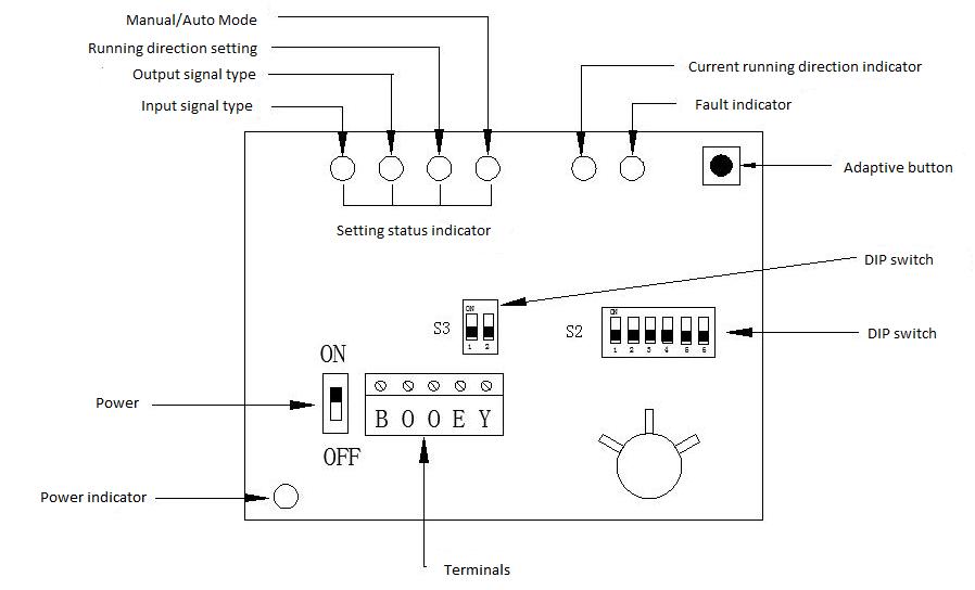
LED Function Description of S6062-05/10 Series Electric Control Actuator
| Position left -> right |
1 |
2 |
3 |
4 |
5 |
6 |
| Number |
LED2 |
LED3 |
LED4 |
LED5 |
LED7 |
LED8 |
| Name |
INPUT |
OUTPUT |
DIR-SET |
MODE |
RUN |
ERROR |
| Description |
Input signal type |
Output signal type |
Running direction setting |
Manual/Auto mode |
Current running direction |
Fault |
| Luminous color |
red/green |
red/green |
red/green |
red/green |
red/green |
yellow |
| Red |
0-10V |
0-10V |
RA |
Auto |
No |
Flash when alarm
|
| Red flashing |
2-10V |
2-10V |
No |
No |
Up |
| Green |
4-20mA |
4-20mA |
DA |
Manual |
No |
| Green flashing |
0-20mA |
0-20mA |
No |
No |
Down |
Remark: The power indicator LED1 is not controlled by the program and remains lit when the main power is on.
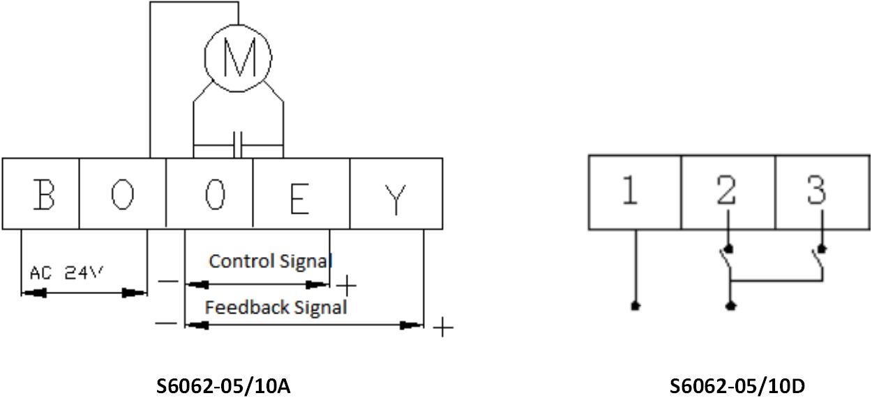
Electrical Wiring Diagram of S6062-05/10 Series Electric Control Actuator
Operation Description of S6062-05/10 Series Electric Control Actuator
1. the operation sequence:
- Connect the drive to the valve body.
- Connect the power and control signal wires.
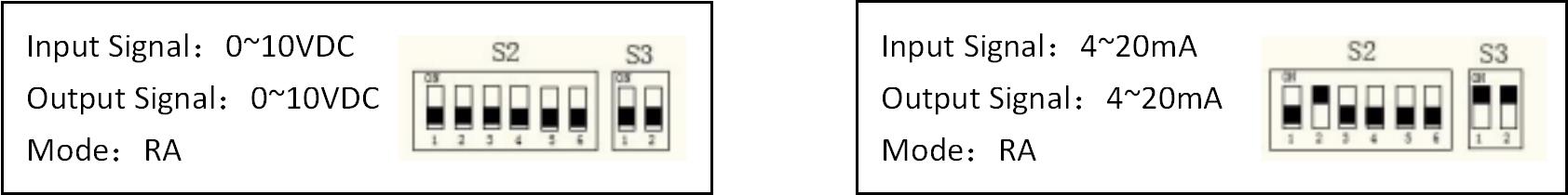
- According to the application conditions, the DIP switch on the board is set to the corresponding position. (See the setting instructions for details)
- Turn on the power, turn on the power switch, the corresponding LED indicator of the driver should be lit, press the “red” auto-tuning button for about 3 seconds to perform the valve stroke self-tuning (see self-tuning instructions for details), electric drive and valve body After the auto-tuning process is completed, the drive enters normal operation and will operate according to the current control signal.
- Do not disconnect the power supply and perform other operations during the drive auto-tuning process.
2. Introduction of valve position feedback signal:
The driver can provide a real-time valve position feedback signal to the outside. The direction of the feedback signal changes always corresponds to the direction of change of the control signal. The type of feedback signal can be set by the DIP switch on the circuit board.
3. Manual operation:
- Open the top cover
- Disconnect the drive power switch and the power indicator should be off.
- Insert the supplied special wrench into the top of the manual shaft
- According to the description of the silkscreen of the upper cover, turn the wrench, rotate clockwise, the spindle will run upwards; turn counterclockwise, the spindle will run downwards.
- After the manual operation is finished, remove the manual wrench, reset the rubber stopper, turn on the power switch, and enter the electric mode.
- When the special wrench is not in use, please put it into the groove of the upper cover and press the wrench down to fix it to avoid loss. Once the manual wrench is lost, it can be operated using a standard 6mm Allen key.
Commonly Control Signal Illustration of S6062-05/10 Series Electric Control Actuator
Self-tuning Process Description of S6062-05/10 Series Electric Control Actuator
- In the non-self-tuning state, press and hold the S1 button in the upper right corner for the about 3S clock to enter the auto-tuning function (when the four setting indicators LED2-LED5 are off, the S1 button can be released). In adaptive phase 1, LED2-LED5 is completely off, the “RUN” indicator flashes green quickly, and the actuator runs down to the lower limit position. After the actuator stops for about 10 seconds, then the second phase is executed, LED2-LED5 is completely off, the “RUN” indicator red light flashes rapidly, and the actuator runs up to the upper limit position.
- The program judges that the data of the self-tuning process is normal, and exits the self-tuning process. The four setting indicators LED2-LED5 return to the normal state, and the driver enters the automatic working state.
- The program judges that the data in the self-tuning process is abnormal and lights up the fault indicator. At this time, it can be reset by re-powering. Try to restart the auto-tuning process. If it still does not end normally, please contact the technician to troubleshoot.
Auto Mode of S6062-05/10 Series Electric Control Actuator
- 4 setting indicators LED2-LED5 display the current main setting status
- The RUN indicator indicates the current drive running direction
- Terminal Y outputs a real-time position signal
Manual Mode of S6062-05/10 Series Electric Control Actuator
- The 5th digit of the actuator S2 dialing code can be set to ON, and the manual control is changed. The setting indicator LED5 turns green. At this time, according to the 6th status bit of the S2 dialing code, it will run to ON and up. The “RUN” indicator will flash red. When it is turned OFF, it will run downwards. The “RUN” indicator will flash green and the drive will run to the limit position. , delay power off to stop the motor.
- Exit the manual mode, you can set the 5th digit of the actuator S2 dial to OFF, switch to automatic control, and set the indicator LED5 to red.
The Manufacturer of HVAC Control Valves and Valve Actuators
The HVAC Actuator Valve Working Principle
HVAC Control Valves and Actuators
 SEARCH