Soloon Controls (Beijing) Co., Ltd. +86-10-67886688
soloon-logo
soloon-logo
Contact Us
S6025 Fluid Level Switch

S6062-18/30A (D) Series Electric Actuator

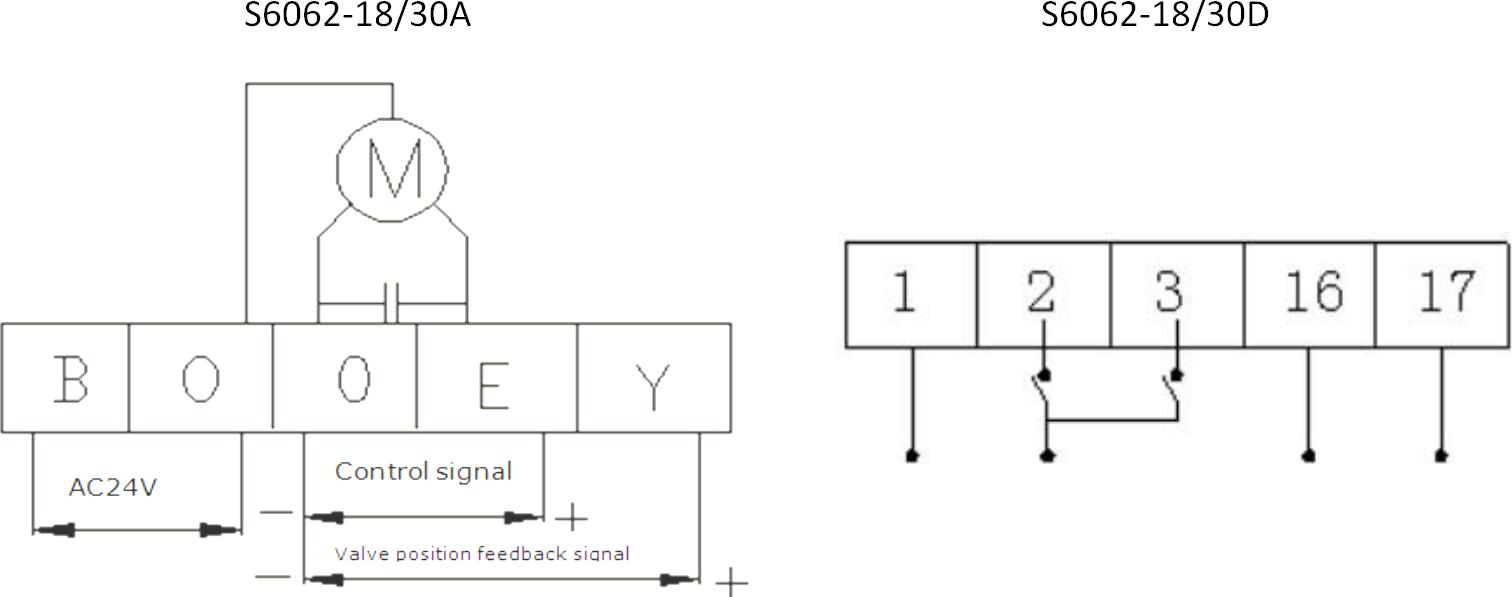
S6062-18/30A, 0~10V, 2~10V or 0~20mA,4~20mA DC control signal for proportional control.

S6062-18/30D,Provides reversible incremental control.

Equipped with manual functions. Suitable for the Johnson and Siemens valve interfaces.

S6062-18/30A (D) Series Electric Actuator

Features of S6062-18/30A (D) Series Electric Actuator


  • Closing force S6062-18A/D is 1800N; Closing force S6062-30A/D is 3000N;
  • The action is transmitted by gears, and the center gear is a roller that rotates around the central axis;
  • Straight stroke indicator;
  • When the drive reaches the limit position, a delay will occur for a period of time to ensure that the valve is opened or closed.


Note of S6062-18/30A (D) Series Electric Actuator


  • When adjusting the medium temperature medium, the grease on the drive needs to be replaced every three months (for example water).
  • In high-temperature media, the grease on the drive needs to be replaced every 30 days.
  • The drive must be protected against water leakage and damage to internal components.
  • The drive should not be covered by insulation material to avoid burning the motor.
  • When repairing the drive, the power must be cut off to prevent damage to the machine or cause leakage to death.
  • Do not touch or attempt to disconnect the line when the power is connected.


Technical Parameters of S6062-18/30A (D) Series Electric Actuator


Model

Parameters

S6062-18A S6062-18D S6062-30A S6062-30D
Power 24VAC±15%
Torque 1800N 3000N
Control signal(Optional) 0~10VDC  2~10VDC

0~20mA   4~20mA

—— 0~10VDC  2~10VDC

0~20mA   4~20mA

——
Control signal input impedance Voltage:100K

Current:250Ω

—— Voltage:100K

Current:250Ω

——
Feedback Signal(Optional) 0~10VDC  2~10VDC

0~20mA   4~20mA

—— 0~10VDC  2~10VDC

0~20mA   4~20mA

——
Feedback output load requirement Voltage:>1K

Current:<=500Ω

—— Voltage:>1K

Current:<=500Ω

——
Power consumption 15VA
Stroke Time(40mm) 120 S 160 S
Maximum stroke 42mm
Manual operation function Standard
Dimensions (standard type) 165*185*340(H)mm
Interface mode Johnson Controls  

s6062-18-30a-d-series-electric-actuator-2


Siemens s6062-18-30a-d-series-electric-actuator-3


High-temperature Drive Model Description of S6062-18/30A (D) Series Electric Actuator


When the drive bracket temperature is higher than 150 °C, it is recommended to use a high-temperature drive, the high-temperature drive product model is S6062- 18/30AG or S6062-18/30DG.


Wiring Diagram of S6062-18/30A (D) Series Electric Actuator


s6062-18-30a-d-series-electric-actuator-4


Type A Drive Operating Instructions of S6062-18/30A (D) Series Electric Actuator


1. Operation sequence

  • Connect the drive to the valve body.
  • Connect the power and control signal lines.
  • According to the application conditions, the DIP switch on the circuit board is set to the corresponding position. (See the setting instructions for details)
  • Turn on the power, turn on the power switch, the LCD screen of the driver and the corresponding LED indicator should be lit. Press the “red” auto-tuning button for about 3 seconds to perform the valve stroke self-tuning (see Self-tuning for details), the electric drive and After the auto-tuning process of the valve body is completed, the drive enters the normal operation and will operate according to the control signal at that time.

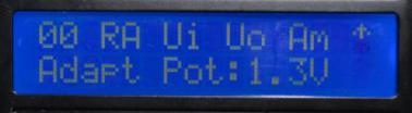
※ Do not disconnect the power supply and perform other operations during the drive auto-tuning process.
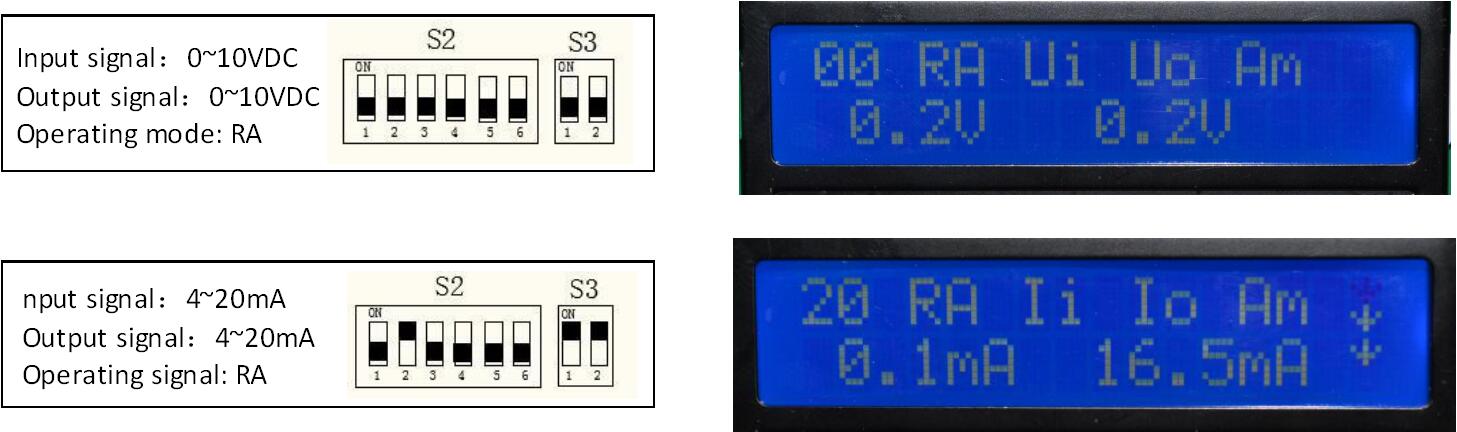
 

2. Valve position feedback signal introduction

  • The driver can provide real-time valve position feedback signal to the outside. The direction of change of the feedback signal always corresponds to the direction of change of the control signal. The type of feedback signal can be set by the DIP switch on the circuit board.


3. Manual operation

  • Disconnect the external power switch of the drive, the power indicator should be off.
  • Open the protective rubber plug on the top of the top cover of the drive to expose the manual operation hole.
  • Insert the special wrench attached to the top of the manual shaft
  • According to the description of the silkscreen of the upper cover, turn the wrench, rotate clockwise, the spindle runs downwards; turn counterclockwise, the spindle runs upwards.
  • After the manual operation is finished, remove the manual wrench, reset the rubber stopper, turn on the power switch, and enter the electric mode.
  • When the special wrench is not in use, please put it into the groove of the upper cover and press the wrench down to fix it to avoid loss. Once the manual wrench is lost, it can be operated using a standard 6mm Allen key.


Conmon Signal setting of S6062-18/30A (D) Series Electric Actuator


s6062-18-30a-d-series-electric-actuator-5


Self-turning Process Description of S6062-18/30A (D) Series Electric Actuator


s6062-18-30a-d-series-electric-actuator-6


  1. Press the self-turning button for about 3 seconds, the LCD will display the interface as shown in Figure 1, the actuator will run downwards to detect the bottom position information. The LED indicator will flash when goes down and will be on when goes up. The second line of the LCD shows the current feedback potentiometer voltage value, which should be reduced as the actuator runs down.
  2. The actuator runs to the bottom, the spindle stops, and the feedback voltage value stops changing, the normal value should be about 0.5-0.8V.
  3. The actuator stays at the bottom about 20S and then starts to run upwards, and detects the top position information. The LED indicator will be on when goes down and will be flash when goes up. The second line of the LCD shows the current feedback potentiometer voltage value, which should be increased as the actuator runs down.
  4. The actuator runs to the top, the spindle stops, the feedback voltage value stops changing, and the normal value is related to the valve stroke size.
  5. The actuator stays at the top about 20 seconds and stores data.
  6. The LCD returns to the automatic operation interface and the auto-turning process


Automatic Control Mode of S6062-18/30A (D) Series Electric Actuator


s6062-18-30a-d-series-electric-actuator-7


  1. The first line is displayed as the setting status of the main DIP switch(see the instruction).
  2. The second line displays the current input and output signals in real-time.
  3. The right dynamic arrow is running status and direction information of the actuator


Manual Control Mode of S6062-18/30A (D) Series Electric Actuator


s6062-18-30a-d-series-electric-actuator-8


  1. Turn the DIP switch S2-5 to the ON (up) position, the actuator enters into the manual control mode, and the LCD display interface is shown in Figure 3.
  2. Turn the DIP switch S2-6 to control the running direction of the actuator.
  3. Turn the DIP switch S2-5 to the OFF position, the actuator returns to the automatic control mode, and the LCD display returns to the automatic control interface.


PCB DIP Switch Setting Instruction of S6062-18/30A (D) Series Electric Actuator


S2 DIP switch Function Setting value function description
1 Sensitivity setting ON HS: High sensitivity
OFF LS: Standard sensitivity
2 Control / valve position feedback signal starting point setting ON 20%: The control/valve feedback signal starts at 20% (used for control/valve feedback signals of 4~20mA or 2~10VDC)
OFF 0: The control/valve feedback signal starts at 0 (used for control/valve feedback signals of 4~20mA or 2~10VDC)
3 Working mode setting ON DA: When the control signal is increasing, the actuator spindle extends out, and when the control signal is decreasing, the actuator spindle retracts.
OFF RA: When the control signal is increasing, the actuator spindle retracts, and when the control signal is decreasing, the drive spindle extends out.
4 Break signal mode setting ON DW: When the control signal is set to voltage type or current type, if the signal line is cut off by this time, a minimum control signal is automatically provided inside the actuator.
OFF UP:1) When the control signal is set to voltage type, if the signal line is cut off at this time, a maximum control signal is automatically provided inside the actuator.

2)When the control signal is set to current type, if the signal line is cut off at this time, a minimum control signal is automatically provided inside the actuator.
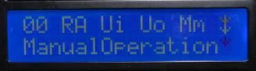
5 Automatic/manual mode conversion ON MO: Manual control mode: The change of the control signal on the terminal is no longer collected, and the running direction is determined by the status of manually dialing the dial code S2-6.
OFF AO: Automatic control mode: Automatic operation and positioning according to the setting and the change of the control signal on the terminal.
6 Manual mode direction ON MO-UP: In manual mode, the actuator spindle runs up.
OFF MO-DW: In manual mode, the actuator spindle runs down.
S3 DIP switch Function Setting value function description
1 Valve position feedback signal type setting ON I-OUT: The valve position feedback signal is current type.
OFF V-OUT: The valve position feedback signal is voltage type
2 Control signal type setting ON I-IN: Control signal is current type
OFF V-IN: Control signal is voltage type


Display Info of S6062-18/30A (D) Series Electric Actuator


Flag bit Function Description
LED indicator POWER POWER It’s always on when the main power of the actuator turn on
UP UP It will flash when the actuator spindle runs up
DOWN DOWN It will flash when the actuator spindle runs down
ERROR ERROR It will be on when the actuator is broken
MM MM It will be on when choosing the manual type
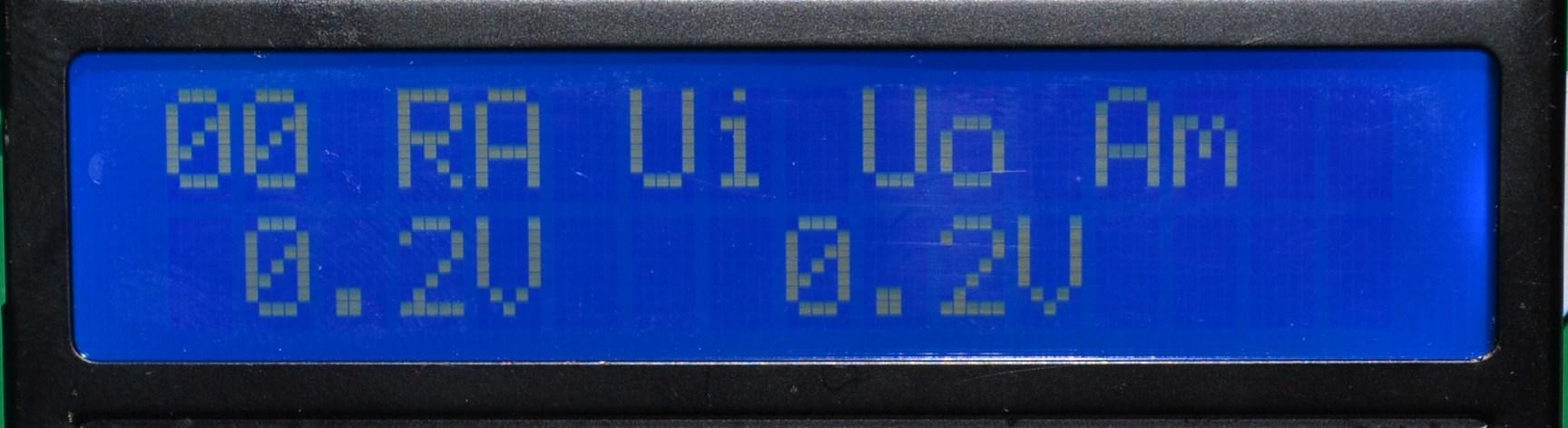
LCD A Signal start point Display the current setting status of the DIP switch S2-2
B Operating mode Display the current setting status of the DIP switch S2-3
C Input signal tyoe Display the current setting status of the DIP switch S3-2
D Output signal type Display the current setting status of the DIP switch S3-1
E Operating mode Display the current setting status of the DIP switch S2-5
INPUT Input signal type Display the currently received control signal in real-time
OUTPUT Output signal type Display the currently output valve position signal in real-time


Accessories of S6062-18/30A (D) Series Electric Actuator

  • Instruction×1
  • handle×1


Johnson interface installation diagram of S6062-18/30A (D) Series Electric Actuator


s6062-18-30a-d-series-electric-actuator-9


Siemens interface installation diagram of S6062-18/30A (D) Series Electric Actuator


s6062-18-30a-d-series-electric-actuator-10


The Manufacturer of HVAC Control Valves and Valve Actuators

The HVAC Actuator Valve Working Principle

HVAC Control Valves and Actuators


Contact Us Product Inquiry
Contact Us
If you are interested in our products.
Please fill in the form & Contact Us.
+86-10-67886688