SEARCH
SEARCH
SEARCH
SEARCH
SEARCH
The S6022 flow switch responds to low fluid flow rates in applications with a pipe size below 1″ to 3″ in diameter. It is a Single-Pole, Double-Throw (SPDT) flow switch that is used in liquid lines carrying water, ethylene glycol, or other liquids that are not classified as non-hazardous. It can be wired to energize one device and energize another device powered from the same source when liquid flow either exceeds or falls below the set flow rate.

| Rated voltage VRated Current A | Power COS ø | 125VAC | 250V AC | |
| No induced load current | 1 | 15 | 15 | |
| Induced load | Full load current | 0.75 | 3.5 | 2.5 |
| Current | Instantaneous current | 0.45 | 21 | 15 |
| Valve Size | Connector | MaxPressure
(Mpa) |
Protection | AllowableMedium Temp. | Wet.(Kg) | Modulating Range of Flow | ||||
| Pipe Size | Min. | Max. | ||||||||
| Flow decrease | Flow increase | Flow decrease | Flow increase | |||||||
| 3″ | 1″-11½ (NPT) | 1.60 | IP65 | -30~120 | 0.6 | 1″ | 2.5 | 4.2 | 8.5 | 8.8 |
| 2″ | 9.5 | 13.7 | 27 | 29 | ||||||
| 3″ | 19 | 27.5 | 50 | 53 | ||||||
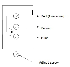
When there is sufficient fluid through the pipe, the loop closes up between red and blue contacts.
* + GPM figures are for a switch with a 6” paddle.
* For 4” and 5” line pipes, the 6” paddle is trimmed to a 4” and 5” length, respectively.
* For switching action, refer to figure 3.
| GPM (m3/hr) Required to Actuate Switch | ||||||||||||||||||||
| Pipe Size (in.) | 1 | 1-1/4 | 1-1/2 | 2 | 2-1/2 | 3 | 4* | 5* | 6* | 8* | ||||||||||
| Minimum Adjustment | Flow increasingred→yellow
closed** |
4.2(1.0) | 5.8(1.3) | 7.5(1.7) | 13.7(3.1) | 18.0(4.1) | 27.5(6.2) | 65.0(14.8)
37.0+ (8.4) |
125.0(28.4)
57.0+ (12.9) |
190.0(43.1)
74.0+ (16.8) |
375.0(85.2)
205.0+ (46.6) |
|||||||||
| Flow decreasingred→blue
closed** |
2.5(0.6) | 3.7(0.8) | 5.0(1.1) | 9.5(2.2) | 12.5(2.8) | 19.0(4.3) | 50.0(11.4)
27.0+ (6.1) |
101.0(22.9)
41.0+ (9.3) |
158.0(35.9)
54.0+ (12.3) |
320.0(72.7)
170.0+ (38.6) |
||||||||||
| Maximum Adjustment | Flow increasingred→yellow
closed** |
8.8(2.0) | 13.3(3.0) | 19.2(4.4) | 29.0(6.6) | 34.5(7.8) | 53.0(12.0) | 128.0(29.1)
81.0+ (18.4) |
245.0(55.6)
118.0+ (26.8) |
375.0(85.2)
144.0 (32.7) |
760.0(172.6)
415.0+ (94.2) |
|||||||||
| Flow decreasingred→blue
closed** |
8.5(1.9) | 12.5(2.8) | 18.0(4.1) | 27.0(6.1) | 32.0(7.3) | 50.0(11.4) | 122.0(27.7)
76.0+ (17.3) |
235(53.4)
111.0+ (25.2) |
360.0(81.8)
135.0+ (30.7) |
730.0(165.8)
400.0+ (90.8) |
||||||||||